The patent of Ukraine: №95130
Author: Tkachenko Yuriy Vladimirovich
Section of the IPC: B21F 25/00 – Barbed wire, mesh, fencing, wire fabrics
Published: 11.07.2011, Bulletin №13/2011
A method of manufacturing a barbed tape – Ukrainian Patent №95130

- A method for producing barbed tape, which is that of a solid wide metal strip produce multiple barbed tapes punctured pair number of oval holes for wide model at a certain distance from the axis of symmetry of each future barbed tape, and recessing staggered bridges between the adjacent edges of the long oval holes to form a large number of pairs of opposing elements. Each element consists of a base and opposing spikes located in the outer sides of the element, and the island each of the studs have angles that are formed between the outer side and the sides of the element, and at recess jumper is formed the outer edge of the element a barbed tapes at the same time automatically is formed the edge of the central portion adjacent barbed tapes. The method is characterized in that oval holes punching and cutting of the bridges between them is carried out in three stages, the first of which occurs the pair of oval holes punching width blanks in two rows. In the second, after leading the model to one step, there is the cutting of the pair of bridges between adjacent tapes of length oval holes. In the third, after leading the model for another half step, recess pair of jumpers that were left for another line location (the checkerboard pattern) in the model.
- Stamp for implementing the method according to point 1, consists of a matrix and a punch, which contains several pairs of punching elements, each of which is composed from two consecutive, oval sectional elements finger punch for punching holes in the model oval. And there are rectangular elements in cross-section, perforating elements for cutting through the bridges between adjacent oval holes in the strip. Which is characterized in that the stamp first arranged in two rows of pairs of oval cross-sectional finger punching elements, followed at a distance of one step of movement of the model located first row of the rectangular cross-sectional breakdown elements for recess of the pair of bridges between adjacent along the length of the blank oval holes which in the region of movement even half step the preform is staggered with respect to the first row of a second row of rectangular cross-sectional portion of punch for cutting through the remaining elements in the model jumpers.
The invention belongs to the metal production, namely to devices and technologies that are used in the production of barbed tapes, barbed wire Egoza and other types of barbed wire that are used as safety barriers designed to prevent unauthorized penetration of sensitive sites.
For the manufacture of barbed tapes often used stamps. Traditionally, the model, which is a continuous metal strip incrementally advance a stamp shaped punches which cut in the strip elements, more oval, with opposite spikes.
Such a method of making barbed tape is most common in the world. For example, a well-known method of manufacturing a sharp and cutting tape, which consists in the fact of a model in form of a continuous narrow metal strips at a distance from its axis of symmetry, both sides uniformly penetrate symmetrical outer open pouch jumper between them constitute great the number of pairs of opposing elements. Each of which consists of a base and an oppositely directed spikes arranged outer sides of the element and the tips of each of the studs has corners which are formed between the outer side and the cell sides. For symmetric punching externally open pouch stamp is used, which consists of a stamp and punch. The punch comprises a punch tools penlight oval shape, which are disposed in the male mold along the same line perpendicular to the direction of movement of the model at step stamp. Such a stamp allows manufacturing of barbed tapes for one full cycle of its operation [see the patent of Ukraine № 41834 of class B21F 25/00 published in 24.04.2001].
The main drawback of the following method of manufacturing the barbed tape is that its application is obtained when only one piece (one sharping and cutting tape), which is not rational. After all, the power of the stamp is usually possible to produce multiple tapes, but the initial blank (continuous narrow strip) in width allows producing only one tape. To increased productivity of the following method it should be used as a starting preform wide metal strip which can be simultaneously produced the multiple barbed tapes.
The main drawback of the known stamp is that it comprises only one pair of punches that is suitable for the manufacture of a piercing and cutting the tape, which, as already mentioned, is not rational. In order to form the stamp grown performance it would be necessary to equip a large number of pairs of punches in the transverse direction.
On this side of the closest in nature and effect, and which is taken as a prototype, there is a method of making barbed tape, consisting of the fact that out of a solid wide metal strip it is made multiple barbed tape by simultaneously punching a pair number of oval-shaped openings on the width of the model in several rows along the length of the model at some distance from the axis of symmetry of each future barbed tape. Simultaneously cutting through staggered webs between the edges of adjacent lengthwise oval holes to form a large number of opposed pairs of elements, each of which consists of a base and an oppositely directed spikes arranged on the outer sides of the element, and the tips of each of the studs are angles that are formed between and outside of the cell sides. And at recess is formed jumper outer edge of one element of barbed tapes at the same time automatically is formed adjacent the edge of the central portion of barbed tapes. To implement this method is used a stamp which consists of a matrix and a punch, and which comprises several pairs of punching elements, each of which is composed with two oval elements finger punch for punching holes in strip oval. Between them there are elements for punching rectangular recess jumpers between general oval holes in the tape, with all the pairs of punch elements arranged in a plane perpendicular to the direction of movement of the model at step stamp. This allows the stamp from a single continuous metal strip to produce a broad multiple barbed cutting bands by simultaneously punching the pair of oval holes quantities across the width of the model. There are several rows along the length of the blank, at a distance from the axis for symmetry of each future barbed belt while simultaneously recessing staggered bridges between adjacent edges along the length of the oval holes to form a large number of opposing pairs of the cutting elements of the tape. This stamp is most similar in nature and effect is achieved and, therefore, taken as a prototype [see the international application № WO00/01501 in Class B 21 F 25/00 published in 13.01.2000].
The main drawback of the following method of manufacturing the barbed tape is that punching operation a significant amount of oval holes and cutting of a large number of jumpers carried out simultaneously in the same location across the width of the model. This leads to excessive load on the model that is too distorted (or even to have a local tears metal or completely broken off. In both cases – is damage to the integrity of barbed tapes – is its invalid defect), and therefore need to introduce a method of compulsory operation alignment barbed belts in the plane for a tight winding them onto spools.
The main drawback of the following stamp has too complicated its design since it between stamps for punching holes are arranged punches for cutting through the jumpers, and all the pairs of punches are difficult without spacing from one another in one zone for the stamp width. This stamp is quite difficult to do, which is why it automatically becomes valuable technological equipment, which, in turn, is reflected in the worse in the cost of products (barbed tapes). Furthermore, random bending (spatial deformation) of several barbed tapes in the zone of finding a large number of punches, during penetration of oval holes and recess jumpers can lead to jamming of the stamp due tamping its matrix deformed piercing and cutting of tapes or completely withdraw failure to stamp out the broken punches.
The basis of the invention is to enhance the adaptability of simultaneous production of several barbed tapes and simplify the design of the stamp while reducing both its cost and the possibility of defects, as well as a simultaneous decrease in the cost of manufacturing by separation in time and space operations punching oval holes and recess jumpers between them by changing the stamp structure, including serial and placement of working elements – punches for each machining operation in different planes (zones) along the entire length of the stamp.
The problem is solved in that the method of manufacturing the barbed tape, which is that of a solid wide metal strip made multiple barbed tapes punctured pair number of oval holes across the width of the model at a certain distance from the axis of symmetry of each future barbed tapes. And recess webs staggered between adjacent edges for long oval holes to form a large number of opposed pairs of elements, each of which consists of a base and an oppositely directed spikes arranged outer sides of the element. Acute each of the studs are the angles that are formed between the outer side and the sides of the element, and is formed in the recess jumpers outer edge of one element of barbed tapes at the same time automatically is formed adjacent the edge of the central portion of barbed tapes. According to the invention, the oval hole punching and cutting of bridges between them is carried out in three stages, the first of which is held in punching the pair of oval holes across the width of the model in two rows. In the second, after leading the model by one step, recess of the pair of bridges between common over the length of the tape oval holes in the third, after leading the model for another half step – cutting of the remaining pair of jumpers on the other line location (the checkerboard pattern) in the model.
The task is also solved by the fact that the punch for producing barbed tape, which consists of a matrix and a punch, which contains several pairs of punching elements, each of which is composed from two consecutive, oval sectional finger punch element to punch oval holes in model. The rectangular cross-sectional punch elements are for cutting through the bridges between adjacent oval holes in the strip. According to the invention, in the stamp first arranged in two rows of pairs of oval cross-sectional finger punch elements, which in the region of one step movement of the model arranged first row part rectangular sectional punching elements for cutting through half the paired webs between total length billet oval holes through which at a distance of a half pitch yet model movement staggered with respect to the first row of the second number of rectangular punch elements in a cut recess for webs which have remained in the model. Step by step conversion solid wide metal strip (billets) in a few barbed-cutting tapes at different times and different areas not how much will increase the total production time (barbed tape still completely manufactured in one cycle of operation of the stamp) and does not increase the size of equipment, however, eliminates all the shortcomings, to abandon a separate operation alignment barbed of tapes before winding them onto spools.
The proposed location of the punch and stamp greatly simplifies it constructively, eliminates the possibility of excessive deformation or twisting barbed tape directly under the stamp, that is, it ensures the prevention of violations of continuity of the process and avoid the reason for the failure of punches. Significant simplification stamp structure reduces its cost, and therefore, manufacturing cost and which is obtained with it. It is understood that in the stamp size, roundness punching elements (punches) may vary depending on the size of barbed tape and its form of cutting elements, the distance between them and etc.
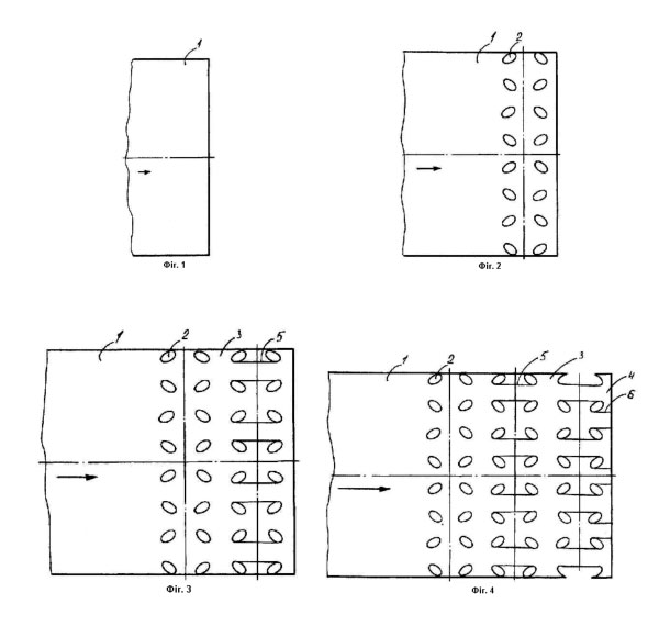
Further essence of the proposed technical solution is explained in conjunction with illustrative material on which images are sequentially process of manufacturing several barbed tape from the continuous wide tape, namely:
- Figure 1 – continuous supply of broad tape (blank) in the working area of the stamp;
- Figure 2 – the first stage is the penetration pair of oval holes across the width of the model in two rows;
- Figure 3 – the second stage is the cutting half of the pair of bridges between general oval holes along the length of the model;
- Figure 4 – the third stage is the recess of jumpers that were on the other line location (the checkerboard pattern) in the model (final separation into individual blanks barbed tapes);
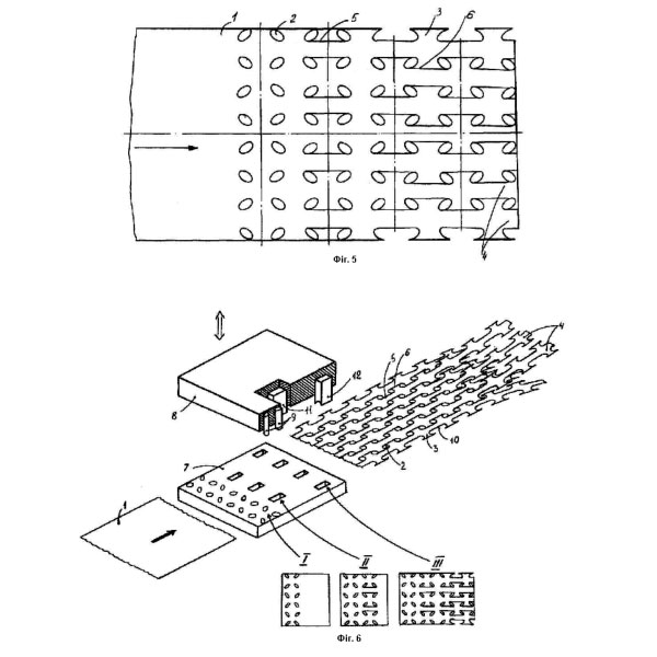
- Figure 5 – the outlet of several ready-barbed tapes from the working area of the stamp;
- Figure 6 – the general view of the stamp and punch stamp proposed in the process of manufacturing multiple barbed tape with one wide model. Single arrows indicate the direction of movement of the model along the working area of the stamp, double – direction of movement of the punch stamp. Roman numerals in Figure 6 show the steps of converting a solid billet of several barbed tapes and under the Roman numerals there are changes of the model at appropriate stages.
The proposed method is the simultaneous production of many barbed tapes as follows. Solid wide band – the model 1 is led into the working area of the stamp. At the first stage in the model 1 twin oval punch holes 2 over the entire width of the model 1 in two rows. After the penetration of these oval holes 2 preform 1 move further into the stamp by one step, which is equal to the width of the elements 3 barbed tapes 4. In the second stage, the recess 5 of the pair of jumpers between the general oval holes 2 along the length of the uncut portion of the model 1. Jumper 5 prevents excessive deformation of the model. At recess 5 jumpers in the second stage, the first position again occurs punching oval holes 2 in the solid portion of the model 1, which when traveling came under the stamp. After a recess of the model 1, 5 jumpers move forward into the stamp for one step. In the third stage, the recess 6 pair of jumpers that were on the other line location (the checkerboard pattern) in the model 1. At this stage, the final separation of the billet 1 into separate barbed tape, which upon further incremental advancement of the model 1, out of the work area stamp and wound onto a bobbin (they are not shown because of the notoriety). At the same time, every step is repeated by punching operations 2 and 5 bridges.
So, step by step production of several barbed tape 4 with consistent separation of the billet 1 in the space thus relieving pressure on the model 1. Proposed Stamp contains a matrix of 7 and 8. The punch 8 comprises a plurality of pairs of successive and different shaped punch elements. The first serially arranged across the stamp in two rows sequentially oval sectional punch elements 9 for punching oval holes 2 in the blank 1. The distance between the rows of oval cross-sectional breakdown elements 9 is determined by the size of the pocket 10 barbed tapes 4. At a distance of one step of movement of the billet 1 is oval in cross-section breakdown elements 9 located across the stamp first part of the rectangular cross-sectional breakdown elements 11 of recess portion pair of jumpers 5 between contiguous to the length of the model 1 oval holes 2, in which the distance is still a half step movement of the billet 1 is staggered second part rectangular in section 12 for the breakdown of elements cutting through the bridges 6, which remained for the final separation of the billet 1 into separate and structurally fully formed barbed tape 4. Lower (working) ends breakdown elements 9, 11 and 12 may be either flat or deep convex punches – it does not matter, since it does not affect the manufacturing technology barbed tape cutting finger punch 4. All elements 9, 11 and 12 have a simple structure in different planes spaced along the length of the stamp, which simplifies its construction and improves maintainability.
If the initial preform 1 was wider than the total width of multiple barbed tape 4, its width or cut to a certain size (for this stamp may have additional cut-off stamps, which are not shown because well-known), or made of edge portions barbed tape with a few unpaired elements (as in the prototype).
The essential difference between the claimed subject matter from the prototype lies in the fact that punching operation and keying webs are separated in time and space due to the diversity in different planes punching stamp member. This difference makes it possible to fundamentally change the technology of producing several piercing and cutting ribbons from one solid billet, in particular to eliminate the deformation of barbed ribbons under the stamp, to simplify the production of the latter. None of the following methods of producing barbed wire cutting may have the above properties, since all operations are performed simultaneously over the entire working area or even possible to produce only one barbed tape.
None of the following stamps for producing barbed tapes can have the above properties, since all its elements are arranged along punch in a plane across the width of the stamp.
The proposed technical solution was tested in practice. The method and the stamp does not contain any elements or steps, that it would be impossible to recreate in the present stage of development of science and technology, in particular the production of barbed tapes. So, it is acceptable for industrial applications, to have certain advantages over the following methods and stamps because of the changes proposed action stamps on the model, which confirms the achievement of the technical result of the object that is claimed. In the well-known sources of information there are not revealed similar methods and stamps for the production of barbed tapes with these essential features in the proposal and therefore relies so that can get legal protection.
The main technical advantages of the proposed technical solutions, in comparison with the prototype are the following:
- no deformation of barbed tapes under the stamp due to the fact that the final separation into individual strips models fulfil on its exit from the stamp;
- there are no need for additional intermediate step alignment barbed tapes due to the absence of excessive deformation of the latter;
- the continuity of the manufacturing technology of barbed tapes from the exclusion of the probability that feeds into the holes of the matrix stamp;
- the simplification of the stamp structure of the spaced punches.
Social benefits from the use of the method and stamp for the manufacture of barbed tapes, in comparison with prototypes, obtained by increasing the number and reliability of the protection of sensitive sites due to the reduction in price of barbed tapes, due to lower cost of the stamp, making them widely available.
The economic effect from the implementation of the invention, in comparison with the prototype, is obtained by reducing the cost of barbed tapes and stamps for production.
After describing the above mentioned techniques for manufacturing the stamp and barbed tape to those skilled in the sphere of production it should be apparent that all of the above is merely illustrative, and not limiting, having been presented by this example. Numerous modifications and other embodiments of the method, in particular the number of received barbed tapes, the use of model edges and etc., may vary in different proportions. Also stamp may vary structurally, in particular the number of punches, their design, the distance between them, the use of edges model or cutting, which of course is within the scope of one of ordinary and natural approaches in the professional area and they are considered as they are within the scope of the technical solutions.
The quintessence of the proposed technical solutions is that transformation of a continuous operation broad model into separate barbed tape occur in stages at different times due to the proposed changes in the stamp design, and it is this fact allows you to purchase the proposed technology and other listed advantages. Change and use of only certain phases of manufacturing techniques of barbed ribbons, and only the individual components of the stamp, of course, limits the range of the above advantages, and cannot rely on new technical solutions in the area of knowledge, as other similar describes a method and a stamp will no longer require no creativity of designers and engineers, and therefore cannot be considered as the results of their creative activity and new intellectual property that require protection by security documents.