Russian Federation Patent: №91015
Author: Tkachenko Yuriy Vladimirovich
Section of the IPC: B21F 25/00 – Barbed wire, mesh, fencing, wire fabrics
Published: 27.01.2010
Stamp for the manufacture of barbed tape – Russian Federation patent №91015

Usage: in a rig, intended for the production of barbed tape, barbed wire Egoza used as safety barriers designed to prevent unauthorized penetration of sensitive sites. The essence: stamp consists of a matrix and a punch, comprising several pairs of punch elements arranged across the width of the stamp, each of which consists of two consecutive oval in cross-section of finger punch members to punch the oval holes in a model, and rectangular in cross-section of punch elements for cutting webs between adjacent oval holes in the model. The first stamp arranged in two rows across the width of the stamp pair oval in cross-section of finger punching elements. Behind them at a distance of one step of movement of the model is the first row of half rectangular in cross-section breakdown of elements to cut half of the bridges between adjacent pairs along the length of the blank oval holes. Behind them at a distance of one and a half steps move the model is staggered with respect to the first row of the second row in the second half of the rectangular cross-section breakdown of elements to cut the remaining jumpers. Technical advantages: no excessive deformation of barbed tapes under the stamp; no additional intermediate step alignment of barbed tapes; the continuity of the manufacturing technology of barbed tapes; simplification of the design of the stamp.
The invention relates to hardware production, and more specifically, to snap, intended for the production of barbed tapes of barbed wire Egoza used as safety barriers designed to prevent unauthorized penetration of sensitive sites.
For the production of barbed tapes often used stamps. The model, which is a continuous metal strip incrementally advance by the stamp, which shaped punches, punch in the strip elements, often oval, with opposite prongs. Such a method of manufacturing barbed tape is the most common in the world.
For example, a method of manufacturing barbed tape, comprising the steps that the model as a continuous narrow metal strip, at a distance from its axis of symmetry, both sides uniformly penetrate symmetrical outer open pockets jumper between them form a large number of opposed pairs of elements, each of which consists of a base and an oppositely directed prongs disposed on the outer sides of the element, and the tips of the prongs are each of the angles formed between the outer side and the side of the element. For symmetric punching externally open pocket stamp is used, which consists of a matrix and a punch configured as a finger punch tools oval, which are arranged in the stamp on the same line perpendicular to the direction of movement of the model at step stamp. Such a stamp allows manufacturing of barbed tapes for one full cycle of its operation. [see the Patent of Ukraine №41834 class B21F 25/00 published in 24.04.2001].
The main drawback of the following stamp is that it comprises only one pair of punches. Therefore, if it is applied only get one item (a barbed tape) that is not rational. After the drive power of the stamp is usually possible to produce multiple barbed tapes, but having only one pair of punches allows to produce only one band. In order to increased productivity famous stamp it must be equipped with a large number of pairs of punches and used as initial blank wide strip from which were manufactured at the same time can be a few barbed tapes.
From this point of view, the closest in its essence and attainable effect is taken as a prototype, is a stamp for manufacturing barbed tape, which consists of a matrix and a punch, comprising several pairs of punching elements, each of which consists of two oval finger punch elements oval for punching holes in the strip, between which is placed the rectangular punch elements for cutting webs between adjacent oval holes in the strip, with all the pairs of punch elements arranged in a plane perpendicular to the direction of step movement of the model under the stamp. This stamp allows one continuous wide metal strip to produce multiple barbed tapes by simultaneously punching the pair number of oval-shaped openings over the width of the model in several rows along the length of the model at some distance from the axis of symmetry of each future barbed cutting tape, and simultaneously cutting in a checkerboard order of the bridges between the adjacent edges of the oval holes along the length to form a large number of opposing pairs of the cutting elements of the tape. Each of these elements consists of a base and an oppositely directed prongs disposed on the outer sides of the element, and the tips of each of the prongs are angles formed between the outer side and the side of the element, and when cutting the webs forms an exterior edge element audio barbed cutting tape and simultaneously automatically formed edge of the central portion adjacent the cutting barbed tape [see international application № O00 / 01501 class V21F 25/00 published in 13.01.2000].
The main disadvantage of this stamp is that the punching operation a significant amount of oval holes and cutting a large number of jumpers carried out simultaneously in one area the width of the model. This, on the one hand, leads to excessive load on the model, which by this excessively deformed or, in general, will have local or metal tears completely severed. Such damage to the integrity of the barbed tapes – is invalid, her marriage. Excessive deformation of ready barbed tapes needs an introduction to the process of mandatory operation of their alignment in the plane for the subsequent dense winding bobbins. On the other hand, a stamp has too complicated structure because it between stamps for punching holes are arranged punches for cutting webs, and all pairs of such complex punches are close distance from one another in one zone for the stamp width. This stamp is quite difficult to make, because then it automatically becomes expensive technological equipment, which in turn is reflected in the worse in the cost of products (barbed tapes). Furthermore, incidental bump (spatial deformation) and several barbed cutting bands in the zone of finding a large number of punches, during penetration of oval holes and fracture of jumpers could lead to jamming of the stamp due to the pushing in its matrix deformed barbed tapes or completely withdraw failure stamp from the broken punches.
The basis of the utility model the task of simplifying the stamp structure while reducing its cost and improve manufacturability simultaneous production of multiple barbed tapes, while reducing the defects by separation in time and space operations punching oval holes and cut the bridges between them by changing the design of the stamp in particular, successive and placement of punches for each machining operation in different zones along the length of the stamp.
This object is achieved in that the stamp for manufacturing barbed cutting tape consisting of a matrix and a punch, comprising several pairs of punch elements arranged across the width of the stamp, each of which consists of two consecutive oval in cross-section of finger punch element to punch oval holes in harvesting, and rectangular in cross-section breakdown of elements to cut the bridges between adjacent oval hole in the model, as proposed in the stamp first arranged in two rows across the width of the stamp pair oval in cross-section of finger punching elements, followed at a distance of one step of movement of the model is the first row half rectangular sectional punching elements for cutting half bridges between adjacent pairs in length billet oval holes, followed by a half distance of movement of the preform step is staggered with respect to the first row of the second row in the second half section of the rectangular punch elements for cutting the remaining jumpers.
It is understood that the dimensions and the roundness of the breakdown of elements can vary depending on the size of the cutting barbed tape and the shape of its cutting elements, the distance between them.
The proposed design of punches and stamps greatly simplifies their design and allows the production of barbed tape sequentially in three stages, the first of which takes place penetration oval pair of holes across the width of the model in two rows, in the second, after leading the blank one step is cutting half of the pair of bridges between adjacent oval holes along the length of the model, on the third, after leading the model for another half step is cutting the remaining pair of jumpers on the other line location (the checkerboard pattern) in the model.
Step by step transformation of a continuous wide billet in several barbed tapes at different times and in different areas and how much does not increase the total production time (barbed tape still completely manufactured in one cycle of operation of the stamp) and does not increase the size of equipment, however, eliminates inherent limitations of the prior art, in particular, to exclude the possibility to deform or curl barbed bands directly under the stamp, that is to prevent discontinuity of the process, give off a separate aligning operation barbed tape before winding them onto spools, greatly simplify manufacturing of the stamp, and this is how to reduce its cost.
Further essence of the proposed technical solution is explained in conjunction with illustrative pictures, which depicts a perspective view of the matrix and the punch stamp and the process of making multiple barbed cutting tapes from a single wide model. Single arrows indicate the direction of movement of the model along the working area of the stamp, double is the direction of movement of the punch stamp. Roman numerals show these steps converting material blank for a few barbed tapes, and under the Roman numerals there is change (transformation) of the model at the appropriate stages.
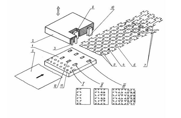
Proposed stamp 1 comprises a matrix and a punch 2. The punch 1 comprises a plurality of pairs of successive and different shaped punch elements. The first turns are located across the stamp in two rows sequentially oval in cross-section breakdown elements 3 for punching oval holes 4 in the preform 5. The distance between the rows of oval in cross-section breakdown elements 3 is determined by the size of the pounches 6 of barbed tape 7. At a distance of one step of movement blanks 5 for the oval cross-sectional penetrative elements 3 is positioned across the stamp first half of the rectangular sectional punching elements 8 to cut the half of the paired webs 9 between adjacent along the length of the preform 5 oval apertures 4, which at a distance a half pitch movement of the model 5 is staggered second half rectangular in cross-section breakdown elements 10 to cut the remaining bridges 9 for the final separation of the model 5 for individual and structurally fully developed barbed tape 7. Lower (workers) ends of the punch elements 3, 8 and 10 may be either flat or concave inside punches – it does not matter, because it does not pours on the technology of manufacturing of barbed tape 7.
If the initial preform 5 was the wider overall width of several barbed tapes 7, it is cut to the width or to a certain size, or are made from edge regions of barbed tape with unpaired elements (like the prototype). For this stamp can be provided with punches additional cutting, which are not shown since common knowledge.
The proposed stamp works as follows.
Solid wide model 5 is fed into the working area of the stamp. Further, in the first stage paired oval punch holes 4 across the width of the model 5 in two rows. For this purpose, finger punching oval in cross-section 3 of the simplest elements of the design. The matrix 1 stamp made corresponding oval holes 11. After punching the model 4 5 moves further into the stamp by one step, which is determined by the length of the pockets 6 of barbed tapes 7. The second step is cutting half of the pair of jumpers 9 between adjacent oval holes 4 to the length of the blank 5. For this purpose, conventional penlight rectangular sectional perforating elements 8 has the simplest structure. The matrix 1 stamp made corresponding rectangular opening 12. When the cutting jumper 9 in the first position again it occurs punching 4. After cutting half jumpers 9 model 5 moves further into the stamp for one the same step. The third step is the cutting of the remaining pair of jumpers 9, but on the other line location (the checkerboard pattern) in the model 5 using the same finger constructively rectangular in cross-section breakdown elements 10. At this stage, the final separation of the model 5 on separate barbed-cutting tapes 7 which, upon subsequent incremental advancement of the preform 5, coming out of the stamp work area, and are wound onto bobbins (not shown since common knowledge). At the same time, each step is repeated punching operations 4 and cutting jumper 8 9 penetrative elements.
Thus, step manufacturing multiple barbed cutting tapes 7 by sequential separation of the preform 5 in the space thus relieving pressure on the model 5, spread perforating elements 3, 8 and 10 of the stamp along the length thereof and so, on the one hand, to simplify its design, with the other – to reduce its construction of excessive deformation of the barbed tapes 7.
The significant difference of the claimed subject from prior art is the fact that the stamp punches for punching and cutting of webs are separated in space along its length. This difference makes it possible to fundamentally change the technology of producing multiple barbed tapes from the same material blank, in particular, to eliminate excessive deformation of barbed tapes under the stamp, to simplify the production of the latter. None of the known stamps for manufacturing barbed tapes cannot have the mentioned properties, since all required processing operations performed blank in one place, or in general allow making only one cutting barbed tape.
The proposed technical solution tested in practice. The stamp does not contain any elements that cannot be replicated at the present stage of development of science and technology, in particular, the production of barbed tapes, therefore, suitable for industrial applications, has certain advantages over the known clichés of proposed changes impacts stamps on the model that confirms the achievement of the technical result of the claimed subject matter in the known sources of information not found similar stamps for manufacturing barbed tapes marked in the offer essential features, but because it is considered to be those that can get legal protection.
The main technical advantages of the proposed technical solutions, in comparison with the prior art, include the following:
- No excessive deformation of barbed tapes under the stamp due to the fact that the final separation into individual strips model takes place on its exit from the stamp;
- No need for an additional intermediate step alignment of barbed tapes due to the absence of excessive deformation of the latter;
- The continuity of the manufacturing technology of barbed tapes from the exclusion of the probability that feeds into the holes of the matrix stamp;
- Simplification of the design of the stamp of the spaced punches and stamps.
Social benefits from the use of the proposed stamp for the production of barbed tapes, as compared with the prototype, are obtained by increasing the number and reliability of the protection of sensitive sites as a result of reduction in price of barbed tapes for reducing the cost of the stamp, making them available for purchase.
The economic effect of the introduction of the utility model as compared with the prior art, obtained by reducing the cost of barbed tapes and stamps to make them.
After the description of the above mentioned stamp for manufacturing barbed tape, those specialists in the given area should be apparent that all of the above is merely illustrative, and do not limit, having been presented by this example. Numerous modifications and other embodiments of the proposed stamp, in particular, the number of punches, their design, the distance between them, the use of edges model or cutting and the like, may vary in different proportions, as well as the stamp may generally vary in design, and clear it within the scope of one of ordinary and natural approaches knowledge in the area and is considered to be within the scope of the technical solutions.
The quintessence of the proposed technical solution is that, thanks to the new stamp, the conversion operation continuous wide billet into separate barbed tapes carried out in stages at different times and this fact allows us to purchase the offer and listed other advantages. The change and the use of only certain elements of the stamp for manufacturing barbed cutting tapes, of course, limits the range of the benefits listed above, and cannot be considered as new technical solutions in the field of knowledge, as some, such as that described stamp will not require any creativity from designers and engineers, and therefore cannot be considered the results of their creative activity and new intellectual property to be protected enforcement documents.
Formula of useful model
Stamp for manufacturing barbed tape consisting of a matrix and a punch, comprising several pairs of punch elements arranged across the width of the stamp, each of which consists of two consecutive oval in cross-section of finger punch members to pierce the oval holes in a model, and rectangular in cross section breakdown elements for cutting webs between adjacent oval holes in a model, characterized in that stamp first arranged in two rows across the width of the stamp pair oval in cross-section of finger punch elements of which, at a distance of one step of movement the model is first row half rectangular in cross-section of punch elements to cut the half of the pair of bridges between the adjacent lengthwise model oval holes, followed by a half distance of movement of the preform step is staggered with respect to the first row of the second row in the second half section of the rectangular punch elements for cutting the remaining bridges.